3. Customization guide
3.1. Customizing the output
Dot2tex offers a few ways of modifying the generated output.
3.1.1. Using styles
The dot language defines the style attribute that can be used to modify the appearance of graphs, nodes, and edges. The style attribute is passed to the rendering backend, and is a powerful and flexible way of customizing the look and feel of your graphs. Using styles requires detailed knowledge of the output format.
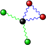
The following example shows how interesting visual results can be achieved with the PGF/TikZ output format. The styles are PGF/TikZ specific. See the user guide for details:
graph G {
    node [shape=circle, fixedsize=True, width="0.2",
          style="ball color =green", label=""];
    edge [style="snake=zigzag, green"];
    a_1 -- c -- a_2;
    c [style="ball color=black"];
    edge [style="snake=snake, blue"];
    node [style="ball color = red", label=""];
    a_3 -- c -- a_4 --a_3;
}
The snake styles only work on straight lines. We therefore have to use the -s option. fdp is used to lay out the graph:
$ fdp -Txdot ball.dot | dot2tex -ftikz -s > balls.tex
The resulting graph is shown below.
Note
Use the straight edge option -s to force the use of straight lines. Otherwise curves will be used to draw even straight lines.
3.1.1.1. Changing arrow types
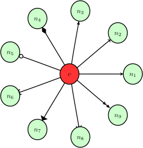
The style attribute can be used to change arrow types. A PGF/TikZ example:
digraph G {
    graph [mindist=0.5];
    node [fixedsize=true, shape=circle, width=0.4, style="fill=green!20"];
    c -> n_1 [style="-stealth"];
    c -> n_2 [style="-to"];
    c -> n_3 [style="-latex"];
    c -> n_4 [style="-diamond"];
    c -> n_5 [style="-o"];
    c -> n_6 [style="{-]}"];
    c -> n_7 [style="-triangle 90"];
    c -> n_8 [style="-hooks"];
    c -> n_9 [style="->>"];
    c [style="fill=red!80"];
}
Rendered with:
$ circo -Txdot pgfarrows.dot | dot2tex -tmath > pgfarrows.tex
You can also set the default arrow style by using the --graphstyle option or d2tgraphstyle attribute:
$ dot2tex -tmath --graphstyle=">=diamond" ex1.dot > ex1gstyle.tex
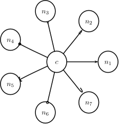
A PSTricks example:
digraph G {
    d2tdocpreamble="\usepackage{pstricks-add}";
    graph [mindist=0.5];
    node [texmode="math", fixedsize=true, shape=circle, width=0.4];
    c -> n_1 [style="arrows=->"];
    c -> n_2 [style="arrows=->>"];
    c -> n_3 [style="arrows=-<"];
    c -> n_4 [style="arrows=-*"];
    c -> n_5 [style="arrows=-{]}"];
    c -> n_6 [style="arrows=-o"];
    c -> n_7 [style="arrows=-H"];
}
Rendered with:
$ circo -Txdot pstarrows.dot | dot2tex -fpst > pstarrows.tex
The above example shows how the d2tdocpreamble attribute can be used to load additional LaTeX packages. You could also use the `--docpreamble option:
$ ... | dot2tex -fpst --docpreamble="\usepackage{pstricks-add}" ...
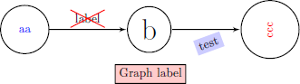
3.1.1.2. Label styles
Node, edge and graph labels can be styled using the special lblstyle attribute. However, this only works for the pgf and tikz output formats.
Labels are drawn using code like:
\draw (157bp,52bp) node {label};
When you specify a lblstyle attribute, the style will be given as a parameter to the node like this:
\draw (157bp,52bp) node[lblstyle] {label};
Example:
digraph G {
    node [shape=circle];
    a -> b [label="label",lblstyle="draw=red,cross out"];
    b -> c [label="test",lblstyle="below=0.5cm,rotate=20,fill=blue!20"];
    a [label="aa",lblstyle="blue"];
    b [lblstyle="font=\Huge"];
    c [label="ccc", lblstyle="red,rotate=90"];
    label="Graph label";
    lblstyle="draw,fill=red!20";
    rankdir=LR;
}
See the PGF and TikZ documentation for more information about styles.
Note
You can use the exstyle attribute in addition to lblstyle. The difference is that exstyle is ignored in preprocessing mode. Useful when using TikZ’ pin and label options and you do not want them to influence the graph layout.
3.1.1.3. Node and edge options
The tikz output format offers an additional way of customizing the output by using the --nodeoptions and --edgeoptions options, or the d2tnodeoptions and d2tedgeoptions graph attributes. The code for generating nodes and edges will then be wrapped in a scope environment like this:
...
\begin{scope}[nodeoptions]
% code for drawing nodes
\end{scope}
\begin{scope}[edgeoptions]
% code for drawing edges
\end{scope}
...
3.2. Customizing edges
The tikz and pgf output formats offers a few additional ways of customizing how edges are drawn and how edge edge labels are placed. These features are tightly integrated with TikZ and detailed knowledge of the output format is therefore necessary.
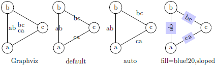
3.2.1. TikZ edge labels
With the --tikzedgelabel option you can bypass the XDOT edge label placement and let PGF and TikZ do the job instead. This can be useful in some cases. However, this only works properly for straight edges and to paths.
Example:
graph G {
    mindist = 0.5;
    node [shape="circle"];
    edge [lblstyle="mystyle"];
    a -- b [label="ab"];
    b -- c [label="bc"];
    c -- a [label="ca"];
}
Without the --tikzedgelabel option the code for placing edges will look something like this:
% Edge: a -- b
\draw [] (28bp,55bp) -- (28bp,75bp);
\draw (40bp,65bp) node[mystyle] {ab};
% Edge: b -- c
\draw [] (51bp,88bp) -- (68bp,78bp);
\draw (66bp,96bp) node[mystyle] {bc};
% Edge: c -- a
\draw [] (69bp,51bp) -- (52bp,41bp);
\draw (53bp,57bp) node[mystyle] {ca};
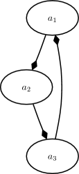
With the tikzedgelabels option the output is simply:
\draw [] (a) -- node[mystyle] {ab} (b);
\draw [] (b) -- node[mystyle] {bc} (c);
\draw [] (c) -- node[mystyle] {ca} (a);
The placement of the edge labels depends on the options passed to the edge label node (in this case mystyle), and the curve used to connect the nodes. Some examples of mystyle values are shown in the figure below. The leftmost graph is rendered without the tikzedgelabels option.
Limitations:
- Works best with straight edges and
topaths - The
headlabelandtaillabelattributes are currently not affected by thetikzedgelabelsoption.
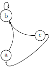
3.2.2. To paths
The topath edge attribute offers a way to override the edges drawn by Graphviz. When a topath attribute is encountered, dot2tex inserts a so called to path operation to connect the nodes. A number of predefined to paths are defined by TikZ, and you can create your own.
Example:
digraph G {
    mindist = 0.5;
    node [shape="circle"];
    a -> b [topath="bend right"];
    c -> b [topath="bend left"];
    c -> a [topath="out=10,in=-90"];
    b -> b [topath="loop above"];
}
Generating the graph with:
$ circo -Txdot topaths1.dot | dot2tex -ftikz > topaths1.tex
yields:
The generated edge drawing code is:
\draw [->] (a) to[bend right] (b);
\draw [->] (c) to[bend left] (b);
\draw [->] (c) to[out=10,in=-90] (a);
\draw [->] (b) to[loop above] (b);
Note
To paths works best with layout tools that generate straight edges (neato, fdp, circo, twopi). The topath attribute overrides the edge routing done by Graphviz. You may therefore end up with overlapping edges.
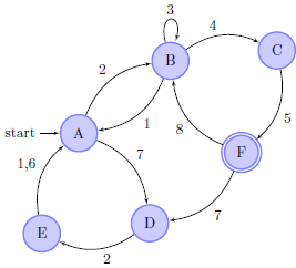
Here is a larger example that uses the automata library:
digraph G {
    d2tdocpreamble = "\usetikzlibrary{automata}";
    d2tfigpreamble = "\tikzstyle{every state}= \
    [draw=blue!50,very thick,fill=blue!20]";
    node [style="state"];
    edge [lblstyle="auto",topath="bend left"];
    A [style="state, initial"];
    A -> B [label=2];
    A -> D [label=7];
    B -> A [label=1];
    B -> B [label=3,topath="loop above"];
    B -> C [label=4];
    C -> F [label=5];
    F -> B [label=8];
    F -> D [label=7];
    D -> E [label=2];
    E -> A [label="1,6"];
    F [style="state,accepting"];
}
Generated with:
neato -Txdot fsm1.dot | dot2tex -ftikz --tikzedgelabels --styleonly
3.3. Color support
All Graphviz color formats are supported, including the RGBA format. Transparency will however only work when using the PGF/TikZ output format.
Named colors are supported, but you have to ensure that the colors are defined in the resulting LaTeX file. The default PSTricks and PGF/TikZ templates load the X11names color scheme defined in the xcolor package. Note that color names in the xcolor package are case sensitive. This is not the case with Graphviz’s color names. Use CamelCase names in your graphs to ensure compatibility with xcolor.
For convenience, a color definition file gcols.tex is distributed with dot2tex. You can find it in the examples directory. This file defines most of Graphviz’s named colors as lower case. Include this file in the preamble if you need it.
3.4. Templates
The output from dot2tex is a list of drawing commands. To render the graphics with LaTeX there’s a need for some boiling plate code. This code can be customized using simple templates. If no template is specified with the --template option, a default template will be used.
The following template tags are available:
<<drawcommands>>- The actual list of drawing commands.
<<figcode>>- Drawing commands wrapped in a figure environment. Note that several important style options are set in the figure environment.
<<bbox>>Bounding box. Example:
(0bp,0bp)(100bp,100bp)The individual parts of the bounding box are available with the tags:<<bbox.x0>><<bbox.y0>><<bbox.x1>><<bbox.y1>>
Note that the bounding box parts are given without any units.
<<textencoding>>- The text encoding used for the output file. Current values are:
-
utf8-latin1 <<docpreamble>>- Document preamble. The content of this tag is set by the
--docpreambleoption ord2tdocpreamblegraph attribute. Useful for including packages and such. <<figpreamble>>- Figure preamble. The content of this tag is set by the
--figpreambleoption ord2tfigpreamblegraph attribute. Useful for setting font sizes and such. <<preproccode>>- Code generated for preprocessing labels.
Three different templates are used by dot2tex for the preprocessing mode, output mode and figure only mode respectively. The following template tags make it possible to use the same template file for all modes.
<<startoutputsection>>and<<endoutputsection>>- Code between these tags is ignored in preprocessing mode.
<<startpreprocsection>>and<<endpreprocsection>>- Code between these tags is ignored in output mode.
<<startfigonlysection>>and<<endfigonlysection>>- Code between these tags is used as a template when using the
--figonlyoption. Ignored in preprocessing and output mode.
Note
Tags that have no value are replaced with an empty string. Insert a % character after a template tag to avoid unwanted line breaks.
3.4.1. Default PGF/TikZ template
\documentclass{article}
\usepackage[x11names, rgb]{xcolor}
\usepackage[<<textencoding>>]{inputenc}
\usepackage{tikz}
\usetikzlibrary{snakes,arrows,shapes}
\usepackage{amsmath}
<<startpreprocsection>>%
\usepackage[active,auctex]{preview}
<<endpreprocsection>>%
<<gvcols>>%
<<cropcode>>%
<<docpreamble>>%

\begin{document}
\pagestyle{empty}
%
<<startpreprocsection>>%
<<preproccode>>
<<endpreprocsection>>%
%
<<startoutputsection>>
\enlargethispage{100cm}
% Start of code
% \begin{tikzpicture}[anchor=mid,>=latex',join=bevel,<<graphstyle>>]
\begin{tikzpicture}[>=latex',join=bevel,<<graphstyle>>]
\pgfsetlinewidth{1bp}
<<figpreamble>>%
<<drawcommands>>
<<figpostamble>>%
\end{tikzpicture}
% End of code
<<endoutputsection>>
%
\end{document}
%
<<startfigonlysection>>
\begin{tikzpicture}[>=latex,join=bevel,<<graphstyle>>]
\pgfsetlinewidth{1bp}
<<figpreamble>>%
<<drawcommands>>
<<figpostamble>>%
\end{tikzpicture}
<<endfigonlysection>>
The <<cropcode>> template tag is available when the --preview option is used. The contents will then be:
\usepackage[active,tightpage]{preview}
\PreviewEnvironment{tikzpicture}
\setlength\PreviewBorder{<<margin>>}
3.4.2. Default pstricks template
\documentclass{article}
% <<bbox>>
\usepackage[x11names]{xcolor}
\usepackage[<<textencoding>>]{inputenc}
\usepackage{graphicx}
\usepackage{pstricks}
\usepackage{amsmath}
<<startpreprocsection>>%
\usepackage[active,auctex]{preview}
<<endpreprocsection>>%
<<gvcols>>%
<<docpreamble>>%


\begin{document}
\pagestyle{empty}
<<startpreprocsection>>%
<<preproccode>>%
<<endpreprocsection>>%
<<startoutputsection>>%
\enlargethispage{100cm}

% Start of code
\begin{pspicture}[linewidth=1bp<<graphstyle>>]<<bbox>>
\pstVerb{2 setlinejoin} % set line join style to 'mitre'
<<figpreamble>>%
<<drawcommands>>
<<figpostamble>>%
\end{pspicture}
% End of code
<<endoutputsection>>%
\end{document}
%
<<startfigonlysection>>
\begin{pspicture}[linewidth=1bp<<graphstyle>>]<<bbox>>
\pstVerb{2 setlinejoin} % set line join style to 'mitre'
<<figpreamble>>%
<<drawcommands>>
<<figpostamble>>%
\end{pspicture}
<<endfigonlysection>>
3.5. Special attributes
Dot2tex defines several special graph, node and edge attributes. Most of them are not part of the DOT language.
texmode- Changes locally how Labels are interpreted.
texlbl- Overrides the current node or edge label.
d2tdocpreamble- Sets the
<<docpreamble>>tag. d2tfigpreamble- Sets the
<<figpreamble>>tag. d2tfigpostamble- Sets the
<<figpostable>>tag. d2tgraphstyle- Sets the
<<graphstyle>>tag. d2ttikzedgelabels- Sets the
--tikzedgelabelsoption. d2tnodeoptions- Sets the
--nodeoptionsoption. d2tedgeoptions- Sets the
--edgeoptionsoption. style- Used to pass styles to the backend. Styles are output format specific, with the exception of the styles defined by the DOT language.
lblstyle- Used to set styles for drawing graph, node and edge labels. Only works for the
pgfandtikzoutput formats. exstyle- The same as
lblstyle, except thatexstyleis ignored in preprocessing mode. topath- Used to set a
topath operation for connecting nodes. Only works for thetikzoutput format. d2talignstrUsed to pass a default alignment string to the PSTricks
\rputcommand:\rput[d2talignstr] ...
d2toptions- Allows you to pass options to dot2tex in the same format as from the command line. The
d2toptionsvalue is parsed in the same way as ordinary command line options.
3.6. Including external dot files
If your input file contains the single line
\input{filename.dot}
dot2tex will load the filename.dot file and convert it. This feature is useful when you want to use the dot2texi package, but don’t want to include your dot code directly in your document.